Plus RS-232 User Manual Page 7
- Page / 16
- Table of contents
- BOOKMARKS
- WITH ±15-kV ESD PROTECTION 1
- DESCRIPTION (CONTINUED) 2
- TERMINAL FUNCTIONS 3
- ESD Protection 4
- Absolute Maximum Ratings 4
- Electrical Characteristics 4
- DRIVER SECTION 5
- Switching Characteristics 5
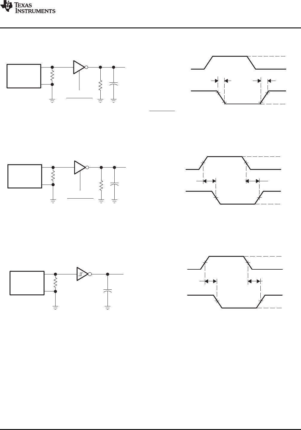
- Figure 1. Driver Slew Rate 7
- Figure 2. Driver Pulse Skew 7
- APPLICATION INFORMATION 9
- REVISION HISTORY 10
- PACKAGE OPTION ADDENDUM 11
- MECHANICAL DATA 15
- IMPORTANT NOTICE 16
Related products and manuals for Projectors Plus RS-232
 (69 pages)
 (15 pages)
(76 pages)
(2 pages)
(25 pages)
(8 pages)
(36 pages)
(138 pages)
(15 pages)
(45 pages)
(19 pages)
(23 pages)
(16 pages)
(72 pages)
(40 pages)
(12 pages)
(36 pages)
(64 pages)
(15 pages)
(76 pages)
(2 pages)
(25 pages)
(8 pages)
(36 pages)
(138 pages)
(15 pages)
(45 pages)
(19 pages)
(23 pages)
(16 pages)
(72 pages)
(40 pages)
(12 pages)
(36 pages)
(64 pages)
© 2020, manymanuals.com. All rights reserved. | 0.073 s |
 Manymanuals.com
 Manymanuals.de
 Manymanuals.fr
 Manymanuals.it
 Manymanuals.pl
 Manymanuals.cz
 Manymanuals.es
 Manymanuals-pt.com
Comments to this Manuals